Anti Vibration Mounts for Gensets
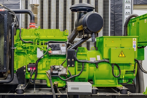
Diesel Generators are naturally prone to inducing Mechanical Vibrations. These undesirable vibrations are caused by the out of balance forces and gas fluctuations of the engine and vary depending on the number of cylinders, firing order and engine configuration. By utilising rubber generator mounts, these undesirable vibrations can be controlled.
Excessive vibration of a Diesel Generator can result in disturbances to adjoining structures and buildings, failure of components such as bearings, and reduced functionality of the Generator, which can ultimately result in breakdown. Vibration Control is therefore an important factor during the design stage and installation stage of the Generating Set.
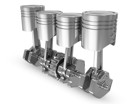
A typical 4 cylinder engine running at 1500RPM (25Hz) will have its dominant vibration harmonic at 2nd Order Frequency (i.e. 50Hz) - This 2nd Order Harmonic is caused by the difference in inertia forces during the upward and downward stroke, due to the mass of the Pistons.
It should be considered that it is not possible to isolate 100% of the vibration caused by the generator, however with modern day balancing of Engines and correctly selected Generator Mounts (Anti-Vibration Mountings) the vibration can be reduced by up to 99%.
Controlling Generator Set Vibration
Assuming that the engine has been correctly balanced, the first consideration should be the supporting structure that the Generator is to be located on. This should be assessed by a structural engineer to ensure sufficient stiffness and rigidity. If the stiffness and rigidity is deemed unacceptable, or where high levels of isolation are required, an inertia base should be considered to increase the mass and hence increase the resistive inertia of the system.
Secondly, the selection of Resilient Mounting should be conducted. This selection should consider the following factors:
- Dominant Vibration Harmonic of the Engine Running Speed of the Generator
- Inertia Forces of the Generator
- Total Weight of the Generator Set Combined Centre of Gravity
- Mobile (Portable) or Static Application
- Environmental Factors (Heat, Contaminants etc)
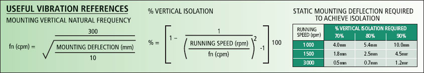
Below you will find the basic formula for calculating the un-damped natural frequency of the resilient mounting, and the level of vertical isolation based on the running speed of the generator. It should be noted that the formula can be used to calculate the isolation based on the primary running speed, or alternatively based on the dominant frequency, in which case the running speed should be multiplied by the corresponding Harmonic to calculate vibration isolation efficiency.
The theory behind the above formula is based on the ratio between the disturbing frequency of the generating set and the natural frequency on the resilient mounting.
Using the earlier example, a 4 Cylinder engine having a running speed of 1500RPM will have a disturbing frequency of 3000CPM or 50Hz, due to its 2nd Order Dominant Harmonic.
Considering a resilient mounting is selected to give a vertical deflection of 2.5mm the resulting vertical natural frequency will be 600CPM or 10Hz. The ratio between the disturbing frequency (50Hz) and the mountings natural frequency (10Hz) dictates the isolation efficiency.
In the above example, the frequency ratio is calculated as 50Hz / 10Hz = Ratio 5.0
The below chart represents the Frequency Ratio against transmissibility (See Fig.3). The horizontal line (at "1") signifies Zero Isolation, whereas anything below the line signifies isolation. Anything above the line signifies resonance.
Pure resonance occurs when the ratio between fn & fd equal 1:1 and isolation occurs when the ratio is higher than 1:1.44, with isolation increasing as the ratio increases.
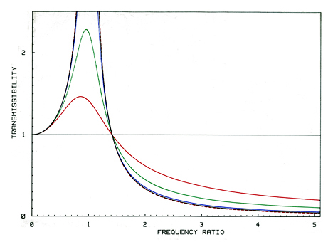
Fig. 3 - Frequency Ratio & Transmissibility
Based on this information a Vibration Control Engineer can calculate the natural frequency (fn) of the generator in all six modes of movement (known as "Six Degrees of Freedom - See Fig.1), consider other factors such as maximum strain on the rubber and the rubber type, and ultimately select a resilient mounting that provides optimum performance and fatigue life.
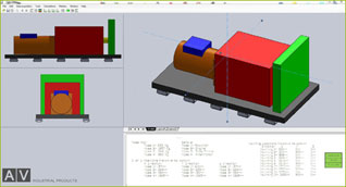
Fig.1 - Six Degree of Freedom Modelling
Basic Theory of Vibration Isolation
As with most reciprocating equipment, the out of balance forces and gas fluctuations of an engine will have a defined frequency harmonic pattern, which is known as the disturbing frequency (fd), in which the dominant frequencies will be generating the highest vibration amplitudes. See Fig. 2 below
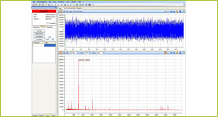
Fig.2 - Typical Vibration Readout of a Generator Set.
The resilient mountings will also have a natural frequency (fn) which is determined by the amount of deflection due to the weight of the equipment.
Vibration reduction occurs by placing a flexible mounting between the Generator and the Supporting Structure. This could be an "In-Skid" installation where the mountings are placed in between the generator and the Skid, or alternatively the mountings can be placed directly under the Skid, fixed to the floor, known as an "outboard" Installation. In some instances manufacturers will decide to use mountings both "In-Skid" and "Outboard" in an attempt to further improve the reduction of vibration.
It should be noted that the above calculations are basic vibration theory which calculate the frequencies in a single degree of freedom, and do not take into account the dynamic stiffness or damping factor of the rubber. For critical applications designers should consult with a Vibration Control Engineer to conduct a six degree of freedom model using dynamic stiffness and damping factors.
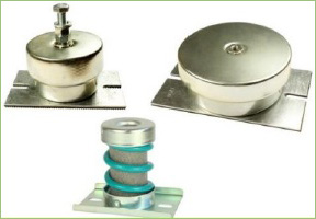
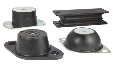
Types of Anti-Vibration Mounting
Anti-Vibration Mountings are typical manufactured in two distinct types - Rubber mounts and Steel Coil Spring Mounts.
Rubber Mounts
have comparatively high damping factors compared to Spring Mounts and also tend to offer lower levels of deflection (typically between 2.5mm-8mm). The increased levels of damping and higher levels of stiffness offered by Rubber mounts provide increased control of the Generator, particularly during Start-Up, Shut Down, or if resonance occurs. This increased damping and control however come at the expense of the vibration reduction which is typically lower than a Spring Mounting, however for majority of application rubber mountings still provide suitable isolation of up to 90%. Rubber Mounts are available with Captive Restraints to ensure a fail-safe design for mobile applications.
Spring Mountings
have a comparatively lower level of damping compared to Rubber mounts and generally provide high levels of deflection (typically 25mm, but can be up to 50mm). This high level of deflection results in extremely low natural frequencies, result in high levels of vibration reduction of up to 99%. However the low stiffness of these products can cause issues during Start-Up, Shut Down, Resonance and Mobile applications. Additional snubbers or restraints can be incorporated to control movement which could otherwise harm the spring mountings and any flexible connections