Technical Info
Anti-Vibration Mounts – ‘What They Are’
The purpose is to reduce the transmission of excitation forces between a vibrating mass and its foundations or supporting structure. An AV mounting acts as a ‘Spring’ - a device that stores energy & subsequently releases it when the applied force is removed. This released energy can be designed to effectively counteract the imposing forces from an external vibrating motion, thereby reducing the transmitted forces and isolating the vibrating equipment. The key to a successful Anti Vibration mounting is to select the spring so that its speed of response – or ‘natural frequency’ is out of phase with the excitation – ‘forcing frequency’ (this is known as the frequency ratio). AV Industrial Products Ltd’s Engineering Rubber is an extremely effective and highly resilient spring material that can return up to 97% of its stored energy, making it the ideal material for anti-vibration mountings, shock absorbers and rubber springs.
Vibration Engineering – ‘How it works’
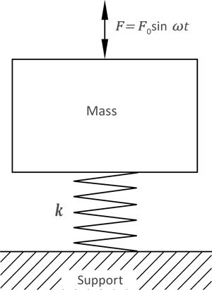
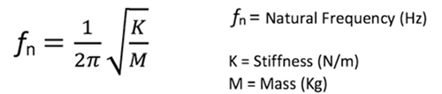
Natural Frequency (fn)
When a material or a suspended body is excited, it will vibrate freely with a ‘natural frequency’ or periodicity until it is allowed to come to rest. The ‘frequency’ and ‘Speed’ of the oscillations will be directly proportionate to the spring stiffness, the mass and its inertia.
If the mass is freely suspended without any restrictions, it will have 6 modes or directions in which it can oscillate – 3 translational; longitudinal, lateral & vertical and 3 rotational; roll, pitch & yaw (these are known as its 6 degrees of freedom or frequencies).
These frequencies can be ‘coupled’, which means by exciting the body in one direction it is possible that all other modes of vibration can be excited, which is not ideal. By positioning the AV mountings on the principle axis (axis of least resistance) or close to the C of G, decoupling of the frequencies can be achieved. It is therefore important to carry out full analysis of the system to avoid resonance conditions and AV Industrial Products Ltd’s Engineering Department can carry out this analysis for you.
Forcing Frequency
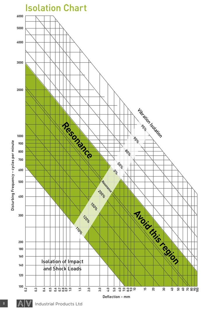
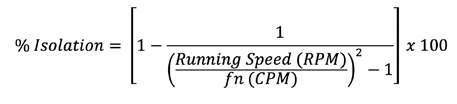
If a suspended body is continuously excited, such as an IC engine, the body will oscillate at the frequency at which it’s being excited at. However, depending on the ratio between the forcing frequency or running speed of the engine and the natural frequency of the AV mounting system, (known as the frequency ratio), the forces (i.e. vibration) being transmitted to the support structure can be reduced and isolated. The higher the frequency ratio the greater the isolation.
To ensure that the anti-vibration mountings are providing isolation, the mountings natural frequency must be at least 1.41 times (i.e. √2) lower than the forcing frequency, and in practice the running speed should be 2 or 3 times greater than the natural frequency of the mountings.
Calculating the Vibration Isolation
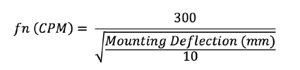
1. Natural Frequency
2. % Isolation
Resonance
When the natural frequency and the forcing frequency are the same, and therefore the frequency ratio is 1, the direction of the forces will coincide & the system will respond by amplifying the disturbing forces into large oscillations. These destructive forces can cause catastrophic failures of equipment and structures, and must be avoided at all costs. AV Industrial Products Ltd’s Engineering Department can predict these resonance conditions and help prevent costly breakdowns.
Harmonic Order
Internal combustion engines and other rotating machinery have a ‘Fundamental’ or primary 1st order running speed. This could be continuous, single speed (e.g. 1500RPM) or variable speed (e.g. 800RPM-2000RPM). However, the machine may have various ‘Harmonics’ or ‘Orders’ of its primary speed, depending of its construction & configuration. The term ‘order refers to the integer multiple of the fundamental speed. For example, a 4 Stroke 4 cylinder engine will have 2nd order out-of-balance forces due to the reciprocating masses of the pistons & connecting rods, and also 2nd order alternating torque fluctuations caused by the variation in gas pressures during combustion. Example; Running Speed 1500rpm gives a 2nd order vibration of 3000rpm or 50Hz (i.e. 2 x 1500rpm). When calculating the isolation efficiency of the antivibration mounting, the harmonic orders of the engine should be taken into account, as this will increase the frequency ratio and better isolation will be achieved.
Isolator
A support, usually one of many in a system, with the purpose of reducing the transmission of vibration and shock from its foundation or support structure. Also known as an AV mounting or Anti-Vibration mounting.
Damper
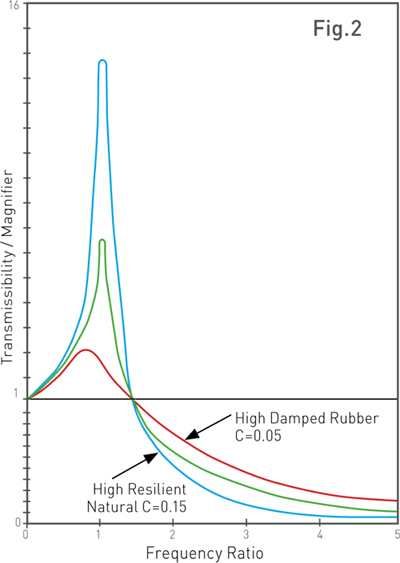
This is a device that dissipates energy. In a rubber product the internal Hysteresis or internal molecular friction converts the energy under cyclic deformation into heat. The effect of damping is to increase dynamic stiffness which reduces the frequency ratio and in turn reduced the isolation efficiency of the mounting – see fig 2. That’s why the majority of AV mountings are manufactured in natural rubber which has a low static (Ks) to dynamic (Kd) stiffness ratio.
However, some damping is useful to control excessive movements when the equipment passes through its resonance frequency during start-up & shut down, and also to control excessive movements when the outof-balance forces are high such as a single cylinder engine. For certain applications, additional external damping is introduced by way of a viscous damper, where the damping force is proportional to the velocity of the vibrating mass. AV Hydromounts give the added benefit of high isolation of transmitted forces, and controlling excessive movement or ‘shake’ at tick-over and low running speeds.
Rubber - ‘What is it’
Versatility
Rubber has amazing properties which can be suited for many applications. By specifying the correct rubber compound, many years of trouble free service life can be achieved. It is an engineering marvel which has been used by humans for 1,000’s of years, and still today, rubber is the material which keeps the world flexible.
- Provide isolation from Vibration, Noise and Shock
- Withstand temperatures from -40°C to +300°C
- Self-extinguishing
- Impermeable to gase
- Elongate to 400% its original length
- Can be repeatedly deformed and will return to its original shape
- Resistant to Fuels, Oils, Acids and other hazardous substances
- Moulded into any shape or form
- Electrically insulating
- Resistant to attack from Ozone and Weathering
- Available in many different colours
- FDA approved for medical and food applications
Rubber Hardness
Hardness is a measure of a materials resistance to indentation. The hardness of Rubber is specified using either the ‘Shore A’ scale or alternatively ‘IRHD’ – International Rubber Hardness Degree’s. Anti-vibration mountings are available from soft 30sh rubber upto 75sh hard rubber. The hardness of a mounting is directly related to a mountings stiffness.
Stiffness
Stiffness is a measure of the force required to deflect a mounting by a given deflection, and is commonly measured in Kg/mm. Rubber is an incompressible material, much like a fluid, therefore the ‘Free Area’ of an AV mountings rubber section, known as the shape factor has a considerable influence on the mountings stiffness, in addition to the rubber hardness. The stiffness of a mounting is directly related to its natural frequency.
Creep
Creep is the continuing deformation whilst under static stress and increases with time. However, most of the Creep deformation will take place within the first 48 hours of the load being applied. It is also accelerated with increased temperature.
Compression or ‘Permanent’ set
When rubber is compressed for a long period of time, it will not fully recover to its original state when the load is removed.
Dynamic Properties
Under repeated cyclic compression of rubber, hysteresis will dissipate some of the energy by converting it into heat. Hysteresis is measured by the difference between the input energy and the energy returned, i.e. the energy loss. Low hysteresis rubber, such as natural rubber provides Low Damping and High Resilience which gives excellent vibration isolation properties. When rubber is subject to cyclic strain, such as vibration, the force required to achieve the same deformation as the static deflection will increase. This increase is known as dynamic stiffness, and the dynamic stiffness is usually 1.1 to 1.4 times higher than the static stiffness for natural rubber, but for some synthetic rubbers this figure can be as high as 8 times.
Rubber Fatigue
Fatigue is defined as ‘a change in properties due to load cycling’ and it is caused by thermal heat buildup from hysteresis; environmental conditions such as Ozone & Oxygen attack; and mechanical crack propagation, any of which can result in a change in
stiffness, Dynamic growth of cracks and Catastrophic failure. Crack initiation can also occur from small surface defects, moulding defects, edge defects at the bonding interface, and from ingredients such as carbon black which do not fully homogenise with the rubber. The flaws can be as small as 25 to 40 microns and there are
When natural rubber is strained, crystals form at the tip of the crack, which has a self-reinforcing effect, suppressing further growth of the crack; i.e. if the energy / stress at the tip of the crack is constant, growth stops. If however the load is relaxed and then reapplied crack growth commences again. In noncrystallising rubber such as SBR, EPDM & NBR the rate of crack growth is time dependant, and therefore under a constant load the crack will continue to grow with time unlike natural rubber. For low stressed applications such as engine mountings and radiator mountings, non-crystallising rubbers give perfectly good service life and are commonly used in many applications. However, the importance of strain induced crystallising natural rubber and non-relaxing load cycling is the most important failure mechanism for parts with repeat load cycling such as springs. AV Industrial Products Ltd have developed ‘HFP™’, a high fatigue resistance Polyisoprene that accommodates the most demanding dynamically fatigued applications.
Manufacturing Methods - ‘How its made’
Metal Preparation
Metal components should be degreased prior to the rubber moulding process to ensure optimum bond strength between the rubber and the metal is achieved, and may be followed by grit blasting or a chemical treatment, such as phosphating, to further improve the bonding conditions.
Bonding
Once achieved by electro brass plating, the rubber bonding process is now achieved by applying a chemical adhesive which can be either a single or a two coat system. The chemical adhesive can be applied by hand brushing, dipping, or spraying (including automated spray booths), depending on manufacturing volumes and complexity of metal components. The physical bond between the rubber and metal takes place during the moulding process, where the heat causes a chemical reaction to occur.
Vulcanisation ‘curing’ of the rubber
Vulcanisation, otherwise known as “Curing”, is the process of creating Cross Links between the polymers molecules, which result in a stable thermoset material which can maintain its mechanical properties and will recover its shape after loading (i.e elasticity). The process of Vulcanisation is achieved during the moulding stage where the compounded rubber, including its various additives, such as Sulphur, are subjected to pressure and heat. The term vulcanisation is named after the god ‘Vulcan’
Compression Moulding
Compression moulding describes the simplest method of manufacturing for rubber components. Rubber blanks are placed in the cavities of the mould, and pressure is applied to the upper and lower half of the mould. At the same time the mould is heated for a predetermined period of time, during which the rubber is ‘Cured’ or Vulcanised. The main advantage of compression moulding are the lower costs of the mould tools.
Transfer Injection Moulding
Transfer moulding is similar in some aspects to compression moulding, however with added benefits. Rubber blanks are placed into a transfer pot which sits above the cavities of the mould. Pressure is then applied to a plunger, which in turn forces the rubber into the cavities of the mould via means of transfer holes to form the finished part. It is subject to the same heating process to ‘Cure’ or Vulcanise the rubber and the process times are comparable to Compression moulding. Due to the better mixing or ‘amalgamation’ of the rubber, better mechanical properties are achieved, making Transfer moulded parts better for flexing & dynamic applications. Tooling costs tend to be more expensive.
Injection Moulding
Injection moulding involves pre-heating and extruding the rubber so that it can be injected directly into the cavities of a closed mould. The pressure and temperature which the rubber is subjected to is much higher than Compression or Transfer moulding and is closely controlled. Advantages of this process are short manufacturing times and higher output, high quality aesthetic finish, and a fully automated manufacturing system. The main disadvantages are the high cost of mould tooling, long tool change over times, and waste material in the injection system, making it unsuitable for low volume production
Rubber Flash & Trimming
During the moulding process the rubber compound flows around the mould and completely fills the cavity, which forms the shape of the finished component. At the same time, a small amount of rubber may also flow between the split lines in the mould tool, and through any spue release holes. This will result in excess rubber, known as flash, on the surface of the finished component. This rubber flash can be removed by Hand Trimming, Tumbling or Cryogenic Deflashing, to improve the aesthetics of the finished product.
Protective Finishes
It is important that exposed metal parts, particularly when using Carbon Steel, have a protective finish that will protect from the environment and inhibit rust. Untreated metals can result in ‘Underbond Corrosion’ which will result in reduced bond strength. Common protective finishes include Zinc Plating, Phosphate, Black Etch Primer and Light Oil Coatings.
Inspection & Quality Control
As an ISO9001 accredited company, our philosophy since 1992 has been to provide high quality engineering components which fully meet specification and achieve the customer’s price targets.
Our wealth of experience in the industry, both in the field of Vibration Engineering and Rubber Engineering, allows us to select materials and manufacturing techniques which are best suited for the application in which the product will be used, ensuring our products meet the required specifications at the very best possible prices.
Using state-of-the-art vibration testing equipment, our finished components are carefully inspected during the quality control process using a variety of techniques to ensure they meet the required standards. Our Testing and Inspection facilities includes both destructive and non-destructive techniques to ensure the correct mechanical properties are achieved, including Bond Strength and Stiffness characteristics.